TC

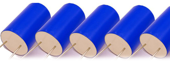
The TC range has been developed give Valve Amplifier designs a new level of responsiveness. Manufactured from polypropylene film, precisely metallised with a unique pattern that greatly enhances self healing, these capacitors offer a dramatic performance improvement over electrolytic types. The TC capacitor’s equivalent series resistance (ESR) and inductance are a fraction of that of an electrolytic, and therefore instantly deliver all their power precisely when it is needed. The dry construction additionally ensures that the performance is retained through out the expected lifetime of the amplifier. In electrolytic capacitors evaporation of the electrolyte reduces capacitance and increases ESR dramatically during the lifetime leading to performance degradation. In professional equipment, frequently shipped in unpressurised aircraft holds, this process is accelerated.
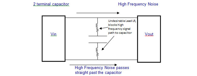
All TC capacitors are un-polarised making assembly simpler and less error prone. The high voltage ratings eliminate the need for series parallel connection. Kelvin lead connections offer an highly effective decoupling of high frequency power supply noise from the signal path when suitably connected.
- TC capacitors are additionally available in 900V, 1100V, 1400V and 1800V should higher voltage ratings be required


Size Chart
| 65 |
450 |
50 |
55 |
4.6 |
20* |
Kelvin |
| 100 |
450 |
50 |
70 |
5.4 |
20* |
Kelvin |
| 175 |
450 |
76 |
55 |
3.0 |
20* |
Kelvin |
| 265 |
450 |
76 |
70 |
2.6 |
20* |
Kelvin |
| 75 |
450 |
50 |
75 |
2.0 |
40 |
M6 / (S) |
| 110 |
450 |
50 |
75 |
2.4 |
40 |
M6 / (S) |
| 230 |
450 |
60 |
110 |
0.9 |
80* |
M6 / (S) |
| 400 |
450 |
63.5 |
145 |
1.0 |
84* |
M6 / (S) |
| 600 |
450 |
76 |
145 |
0.9 |
94* |
M6 / (S) |
| 750 |
450 |
84 |
145 |
0.8 |
98* |
M6 / (S) |
| 50 |
600 |
50 |
55 |
5.4 |
20* |
Kelvin |
| 70 |
600 |
50 |
70 |
6.0 |
20* |
Kelvin |
| 130 |
600 |
76 |
55 |
3.2 |
20* |
Kelvin |
| 200 |
600 |
76 |
70 |
2.8 |
20* |
Kelvin |
| 55 |
600 |
50 |
75 |
2.4 |
39 |
M6 / (S) |
| 85 |
600 |
50 |
75 |
2.8 |
29 |
M6 / (S) |
| 175 |
600 |
60 |
110 |
1.0 |
78* |
M6 / (S) |
| 300 |
600 |
63.5 |
145 |
1.1 |
81* |
M6 / (S) |
| 440 |
600 |
76 |
145 |
0.9 |
91* |
M6 / (S) |
| 560 |
600 |
84 |
145 |
0.9 |
95* |
M6 / (S) |
| 39 |
800 |
35 |
47 |
6.1 |
20* |
Kelvin |
| 55 |
800 |
35 |
56 |
7.1 |
20* |
Kelvin |
| 100 |
800 |
45 |
56 |
3.4 |
20* |
Kelvin |
| 150 |
800 |
45 |
56 |
3.7 |
20* |
Kelvin |
| 45 |
800 |
50 |
75 |
2.7 |
38 |
M6 / (S) |
| 70 |
800 |
50 |
75 |
3.1 |
34 |
M6 / (S) |
| 130 |
800 |
60 |
110 |
1.3 |
67* |
M6 / (S) |
| 230 |
800 |
63.5 |
145 |
1.3 |
74* |
M6 / (S) |
| 340 |
800 |
76 |
145 |
1.1 |
85* |
M6 / (S) |
| 430 |
800 |
84 |
145 |
1.0 |
90* |
M6 / (S) |
| 25 |
1100 |
50 |
50 |
7.8 |
20* |
Kelvin |
| 36 |
1100 |
50 |
65 |
8.8 |
20* |
Kelvin |
| 65 |
1100 |
76 |
50 |
4.1 |
20* |
Kelvin |
| 100 |
1100 |
76 |
65 |
4.3 |
20* |
Kelvin |
| 28 |
1100 |
50 |
75 |
3.5 |
35 |
M6 / (S) |
| 42 |
1100 |
50 |
75 |
3.8 |
31 |
M6 / (S) |
| 85 |
1100 |
60 |
110 |
1.5 |
64* |
M6 / (S) |
| 145 |
1100 |
63.5 |
145 |
1.5 |
70* |
M6 / (S) |
| 220 |
1100 |
76 |
145 |
1.3 |
81* |
M6 / (S) |
| 280 |
1100 |
84 |
145 |
1.1 |
87* |
M6 / (S) |
ESR - when measured at 10kHz. Imax - Max rms ripple current at 1kHz in 40°C ambient, still air for T hotspot = 70°C
* Imax limited by the lead capacity
Component Outline

Ordering Details
TC 20u K 600 S
| K |
Tolerance (10%) |
700V |
Rated dc voltage |
| S |
Base stud 6- M6 (optional) |
|
|
TC Power Supply Capacitors - Supplemental Information
Click to show/hide
When ClarityCap introduced the MR Audio Capacitor it was the culmination of a 3 year research program with the world renowned Acoustics Research Centre at the University of Salford. The MR range defined a new standard in acoustic performance and has been widely adopted through out the industry.
Following this remarkable success the ClarityCap engineers, turned their attention to power supply capacitors. Film capacitors have not traditionally been able to offer sufficient energy density to provide the necessary stability at reasonable cost or size for a power supply or valve amplifier circuit. Historically electrolytic capacitors have been the only viable alternative. However there are many disadvantages: Polarised; Limited to low voltage operation; high inductance; high impedance.
With the launch of the TC range CalrityCap have again laid down the new standard:
Energy density
Development of new highly specialised films have allowed significant enhancements to the available energy density. The films used in TC capacitors provide energy densities which when combined with the other performance characteristics not only make the TC capacitors an alternative to electrolytic technology, they take audiophile power supply filtering to new levels of performance.
Impedance
In circuit impedance of a capacitor is derived from dielectric loss at the operational frequencies, the electrode impedance and inductance, which is a function of electrode thickness and width and lead connection. TC capacitors use a polypropylene dielectric which has been proven over time to have outstanding low losses well suited to audiophile applications. Careful consideration to electrode thickness and width have resulted in the TC range offering incredibly low circuit impedance. Ultimately the low impedance translates to incredible dynamic response with the capacitor able to source and sink current at far higher rates than competing technologies.
4 terminal connections
Recognising several of the limitations above some Electrolytic capacitor manufacturers offer a four terminal arrangement that improves the basic circuit performance via the addition of additional terminals to enhance current flow to and from the capacitor and ensure high frequency signals were delivered to the electrodes of the capacitor. The smaller capacitance values of the TC range benefit from this construction technique, dramatically improving the ability of the capacitor to filter high frequency noise. See diagrams below.
Inductance
Metallised film capacitors have long been recognised for their incredibly low inductance. In an electrolytic capacitor a limited number of connections between the terminals and electrode foils are made. Metallised film capacitor’s electrodes connected to the terminals via a thermal arc spray process that ensures every part of the electrode is connected to the terminal, thus effectively eliminating inductance in the winding itself.
Operating Voltage range
Electrolytic capacitors have a technological limit that prevents operation above 500-600V. In applications requiring higher voltages such as valve biasing it has been necessary to construct filter capacitor banks with series connection of several components to achieve the required voltage. Series connected capacitors require balancing resistors to prevent uneven leakage paths forcing too high a voltage on any one single component. The TC range of film capacitors are available from 450V to 1800V eliminating the requirement for series connection. TC capacitors are also un-polarised preventing costly (and sometimes dangerous) mistakes of connection electrolytic capacitors in the incorrect polarity.

All TC capacitors are un-polarised, for 4 terminal capacitors the leads can be indentified as follows.
Wide lead spacing, A, separates positive and negative terminals
Narrow lead spacing B, indicates Kelvin leads of the same polarity for separation of input and output current.


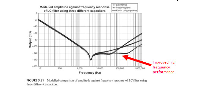
Enhanced high frequency performance of a four terminal film capacitor used in a valve amplifier power supply circuit.
SOURCE: Valve Amplifiers, Morgan Jones, 2011. ISBN - 13: 978-0080966403


